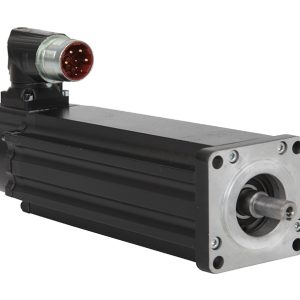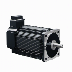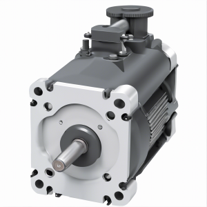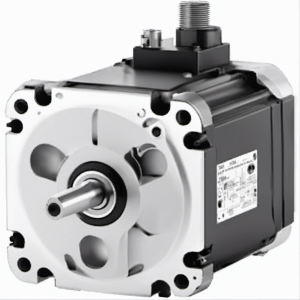
VPL-A1002F-PJ12AS KINETIX; PERMANENT MAGNET ROTARY MOTOR, Servo Motor | Allen Bradley
Type number: VPL-A1002F-PJ12AS, Part No.: VPLA1002FPJ12AS, from manufacturer: Allen Bradley, Catagory: Kinetix VP Servo Motors Drives & Motors, VPL Low Inertia Motors
della101@163.com
| Module No. | VPL-A1002F-PJ12AS |
| Product name | 240V AC, 100mm Bolt Circle Frame Size, 2 (Two) Magnet Stacks, 4500 RPM Rated Speed, Multi-turn Encoder, Keyed Shaft, SpeedTec Right … |
| Product description | VPL-A1002F-PJ12AS KINETIX; PERMANENT MAGNET ROTARY MOTOR, Servo Motor | Allen Bradley |
| Part number | VPLA1002FPJ12AS |
| Allen Bradley recommendation product | VPL-A1002F-PJ14AA VPL low inertia motor | Allen Bradley |
| Voltage | 230 VAC, 240 VAC, 480 VAC |
| Manufacturer | Allen Bradley |
| Country of origin | United States |
| Warranty | 1-2 year |
| Shipping Method | 1.Ship worldwide, usually 5-7 days. 2. We use DHL, FedEx, UPS,TNT |
| Remark | If you need a specific firmware or series relating to VPL-A1002F-PJ12AS, please call or email us, we probably have it in our large inventory. |
VPL-A1002F-PJ12AS KINETIX; PERMANENT MAGNET ROTARY MOTOR, Servo Motor | Allen Bradley
Catalog Number Explanation
(1) This encoder option is available with only VPL-A/B100xx, VPL-A/B115xx, VPL-A/B130xx, and VPL-B165xx motor frame sizes.
(2) This encoder option is available with only VPL-B063xx and VPL-B075xx motor frame sizes.
(3) Rated speed hierarchy is only for comparative purposes. Use Motion Analyzer software to size and select motors for your application, and/or the torque/speed curves in the Kinetix 5500 Drive System Design Guide, publication
KNX-RM009 and the Kinetix 5700 Drive System Design Guide, publication KNX-RM010.
(4) Refer to Motor Dimensions (063 mm and 075 mm frame sizes) on page 7 and Motor Dimensions (100…165 mm frame sizes) on page 8 for dimensional changes (L, LB, LD, and LE) that result from the number of magnet stacks.
Before You Install the Motor
Perform these inspection steps and review the guidelines for shaft seals, couplings and pulleys, and electrical noise prevention.
1. Remove the motor carefully from its shipping container.
2. Inspect the motor for any damage.
3. Examine the motor frame, front output shaft, and mounting pilot for any defects.
4. Notify the carrier of shipping damage immediately.
Remove the Shaft Cap
Remove the protective cap installed on the motor shaft with your hand or by prying it off with a screwdriver. Do not use a hamm er or other tools as
they can damage the motor shaft.
ATTENTION: Do not attempt to open and modify the motor beyond changing the connector orientation as described on page 5. Only a qualified Rockwell
Automation employee can service this motor.
VP L – x xxx x x – x x 1 x A x
Factory Options
A = Standard
S = Shaft seal
Mounting Flange
A = IEC metric, free mounting holes (type FF)
Brake
2 = No Brake
4 = 24V DC Brake
Shaft Key
J = Shaft key
K = Smooth shaft
Connector
1 = Single SpeedTec DIN connector, right angle, 325° rotatable
Feedback
C = 18-bit absolute single-turn digital encoder (Hiperface DSL protocol)
P = 18-bit absolute multi-turn (4096 revolutions) digital encoder (Hiperface DSL protocol)
Q = 23-bit absolute multi-turn digital encoder (Hiperface DSL protocol) SIL2/PLd rated, 12-bit secondary safety channel (1)
W = 18-bit absolute multi-turn digital encoder (Hiperface DSL protocol) SIL2/PLd rated, 9-bit secondary safety channel (2)
Rated Speed (3)
A = 1500 rpm D = 3000 rpm M= 6000 rpm
B = 2000 rpm E = 3500 rpm T = 6750 rpm
C = 2500 rpm F = 4500 rpm U = 8000 rpm
Magnet Stack Length (1, 2, 3, 4, 6 stacks) (4)
Frame Size – Bolt Circle Diameter (BCD)
063 = 63 mm 115 = 115 mm
075 = 75 mm 130 = 130 mm
100 = 100 mm 165 = 165 mm
Voltage Class