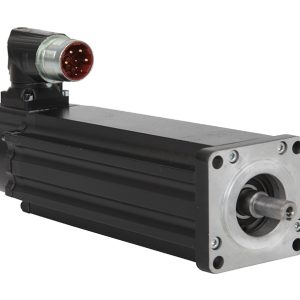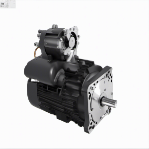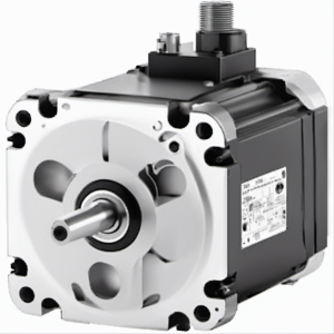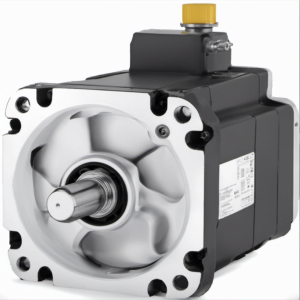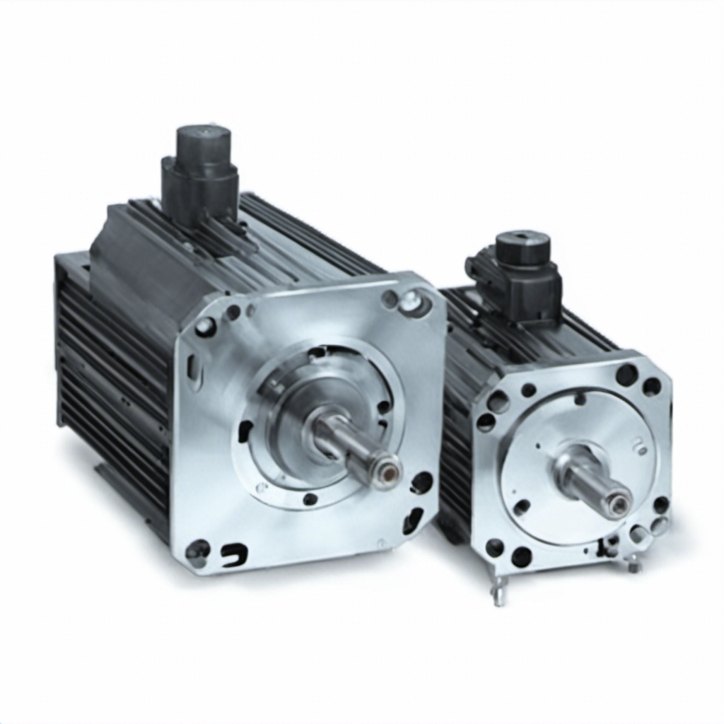
VPL-A1002C-CJ12AS Servo Motor, Low Inertia | Allen Bradley
Type number: VPL-A1002C-CJ12AS, Part No.: VPLA1002CCJ12AS, from manufacturer: Allen Bradley, Catagory: Kinetix VP Servo Motors Drives & Motors, VPL Low Inertia Motors
della101@163.com
| Module No. | VPL-A1002C-CJ12AS |
| Product name | 240V AC, 100mm Bolt Circle Frame Size, 2 (Two) Magnet Stacks, 2500 RPM Rated Speed, Single-turn Encoder, Keyed Shaft, … |
| Product description | VPL-A1002C-CJ12AS Servo Motor, Low Inertia | Allen Bradley |
| Part number | VPLA1002CCJ12AS |
| Allen Bradley recommendation product | VPL-A1002C-CJ14AA KINETIX; PERMANENT MAGNET ROTARY MOTOR, Servo Motor | Allen Bradley |
| Voltage | 230 VAC, 240 VAC, 480 VAC |
| Manufacturer | Allen Bradley |
| Country of origin | United States |
| Warranty | 1-2 year |
| Shipping Method | 1.Ship worldwide, usually 5-7 days. 2. We use DHL, FedEx, UPS,TNT |
| Remark | If you need a specific firmware or series relating to VPL-A1002C-CJ12AS, please call or email us, we probably have it in our large inventory. |
VPL-A1002C-CJ12AS Servo Motor, Low Inertia | Allen Bradley
Follow these steps to rotate a connector to a new position.
1.Mount and fully seat a mating cable on the motor connector.
This provides a larger area to grasp and extends the leverage force.
2.Grasp the mated connector and cable plug with your hands and slowly rotate the motor connector into the new position. 3.Remove the cable plug after the connector is aligned.
Install the Motor
Perform these steps to install the motor.
| ATTENTION:Damage can ocur to the motor bearings and the feedback device if sharp impactis applied to the shaft during installation of couplings and pulleys. Damage to the feedbadk device can result from applying leverage to the motor mounting face when removing devices mounted on the motor shaft.
Do not strike the shaft,couplings,or pulleys with tools during installation or removal.Use a wheel puller,to apply pressure from the user end of the shaft,when attempting to remove any device from the motor shaft. |
1.Leave enough space around the motor so it can disipate heat and stay within its specified operating temperature range.
See Environmental Specifications on page 22 for the operating temperature range.Do not enclose the motor unless forced air is blown
across the motor for cooling.A fan that blows air across the motor improves its performance.Keep other heat producing devices away from the motor.
2.See Load Force Ratings on page 11 to determine the radial and axial shaft load limitations of your motor.
3.Install the motor with the connector positioned beneath the motor housing.
This position can provide better environmental protection for the connector.
BURN HAZARD: Outer surfaces of the motor can reach a high temperature,125℃(257°F),during motor operation.
Take precautions to prevent acaidental contact with hot surfaces.Consider motor surface temperature when selecting motor mating connections and cables.
4.Mount and align the motor.
5.Atach the single moror cable that transmits the power,feedback,and brake signals as descrtbed below.
a.Carefully align the cable connector with the motor connector.
The flat surface on the top of the motor connector and the flat surfaces on the cable connector must align for the cable connector to mate with the motor connector.
| ATTENTION: Keyed connectors must be properly aligned and hand-tightened.
Do not use tools,or apply excesive force,when mating the cable to the motor connector.If the connectors do not go together with light hand force, realign and try again. |
|
| b.Hand-tighten the knurled collar one-quarter turn to fully seat the cable connector. | |
| ATTENTION: The overall shield on the single motor cable must be grounded to obtain an effective encoder signal.
Theencoder data signalis transmitted through an impedance-matthed twisted wie pai that requies eftective shielding for opimum performance. Be sure thereis an effective connection between the single motor cable shield and the drive system ground. |
|
c.Form a drip loop in the cable to carry liquids away from the connectors.